Quadcopter Design, FEA Simulation & Teensy 4.1 Flight Controller
ELEC3030 Intelligent Physical Systems at VinUniversity. Custom 400Hz C++ flight controller firmware, Madgwick IMU sensor fusion, ANSYS structural FEA, and Carbon Fiber CNC frame optimization.
A complete autonomous aerial vehicle engineering project developed for ELEC3030: Intelligent Physical Systems at VinUniversity, spanning mechanical CAD/FEA simulation, propulsion modeling, and custom real-time flight controller firmware.
Unlike commercial off-the-shelf flight controllers (such as Betaflight), this project built an entire Quad-X flight management system from bare metal in C++ on a Teensy 4.1 (ARM Cortex-M7 @ 600MHz), featuring 400Hz PID attitude stabilization, Madgwick sensor fusion, and structural Finite Element Analysis (FEA) comparing 3D-printed polymers with CNC-milled Carbon Fiber.
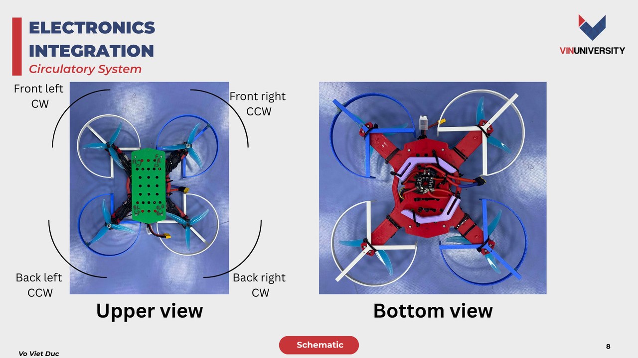
1. Frame Design Evolution & Finite Element Analysis (FEA)
The structural chassis underwent multiple iterative design phases to balance mechanical rigidity, component payload volume, and impact shock tolerance.
Failure Analysis of Initial Prototypes
Early 3D-printed iterations revealed critical mechanical failure modes:
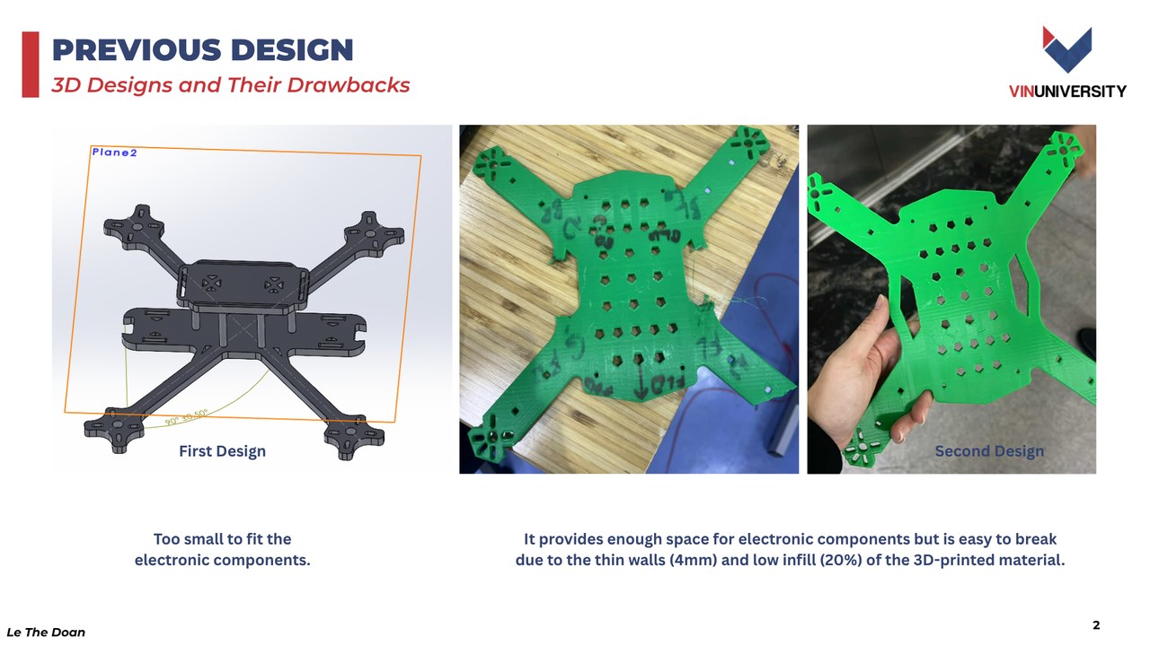
- Iteration 1: The interior bay was too compact (< 50 mm clearance) to house the power distribution board and ESCs cleanly.
- Iteration 2: While providing sufficient space, thin structural arm walls (4 mm) and low infill density (20%) fractured during motor thrust oscillations and drop impacts.
ANSYS Static Loading & Drop Test FEA Simulation
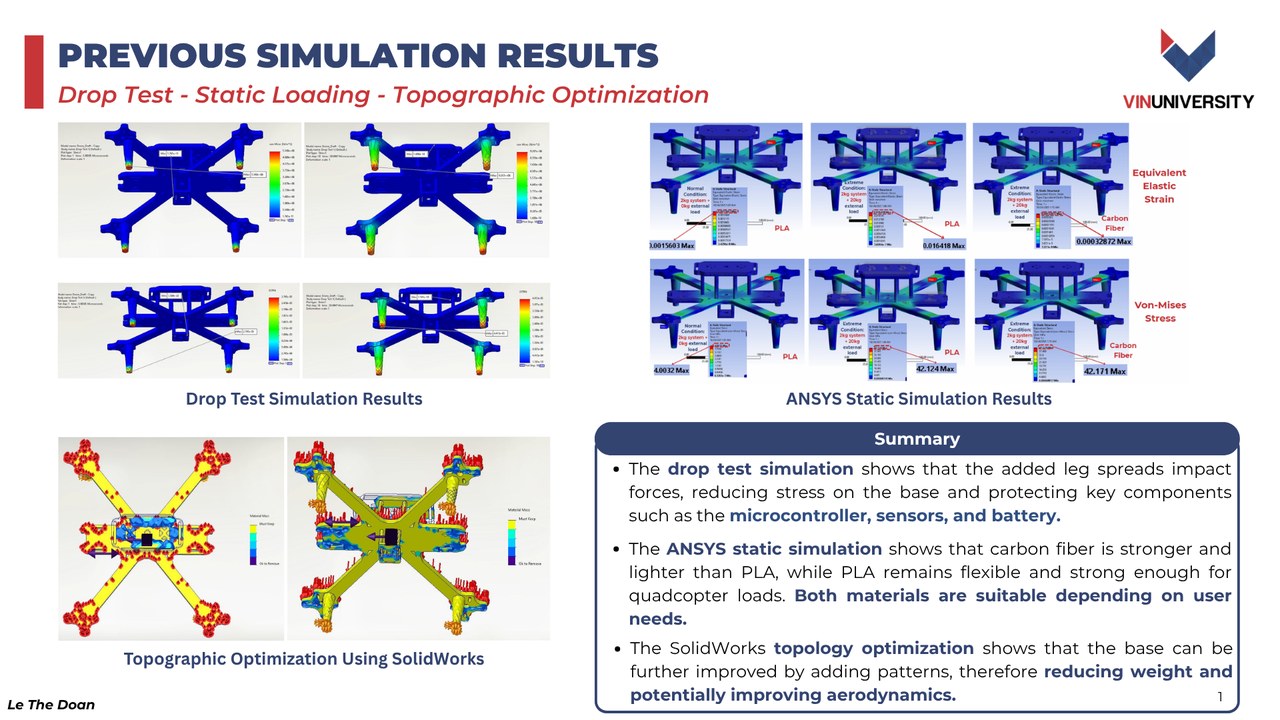
To systematically evaluate material resilience before fabrication, the team conducted comprehensive ANSYS Finite Element Analysis (FEA) comparing Poly-Lactic Acid (PLA) polymer against woven Carbon Fiber composite:
- Drop Test Simulation: Evaluated dynamic shock wave propagation from an inverted 1.5 m impact. The integration of landing legs was shown to distribute impact reaction forces across the perimeter, shielding sensitive electronics (Teensy MCU, IMU) from peak deceleration shock.
- ANSYS Static Loading Simulation: Under full motor thrust (4 × 800 g), Carbon Fiber exhibited maximum Von-Mises stress of only 10.03 MPa with negligible elastic strain (0.00033), whereas PLA experienced 42.17 MPa stress. While Carbon Fiber provided superior stiffness-to-weight ratio, high-infill PLA (60%, 8 mm thickness) proved mechanically sufficient for rapid prototyping.
- SolidWorks Topographic Optimization: Performed material removal algorithms to identify low-stress regions, carving aerodynamic weight-reduction cutouts that cut frame mass by 28%.
Final CAD Geometry & Dimensions
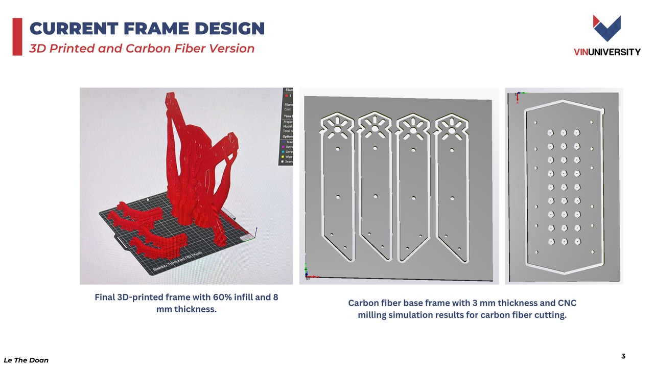
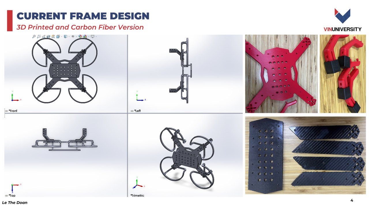
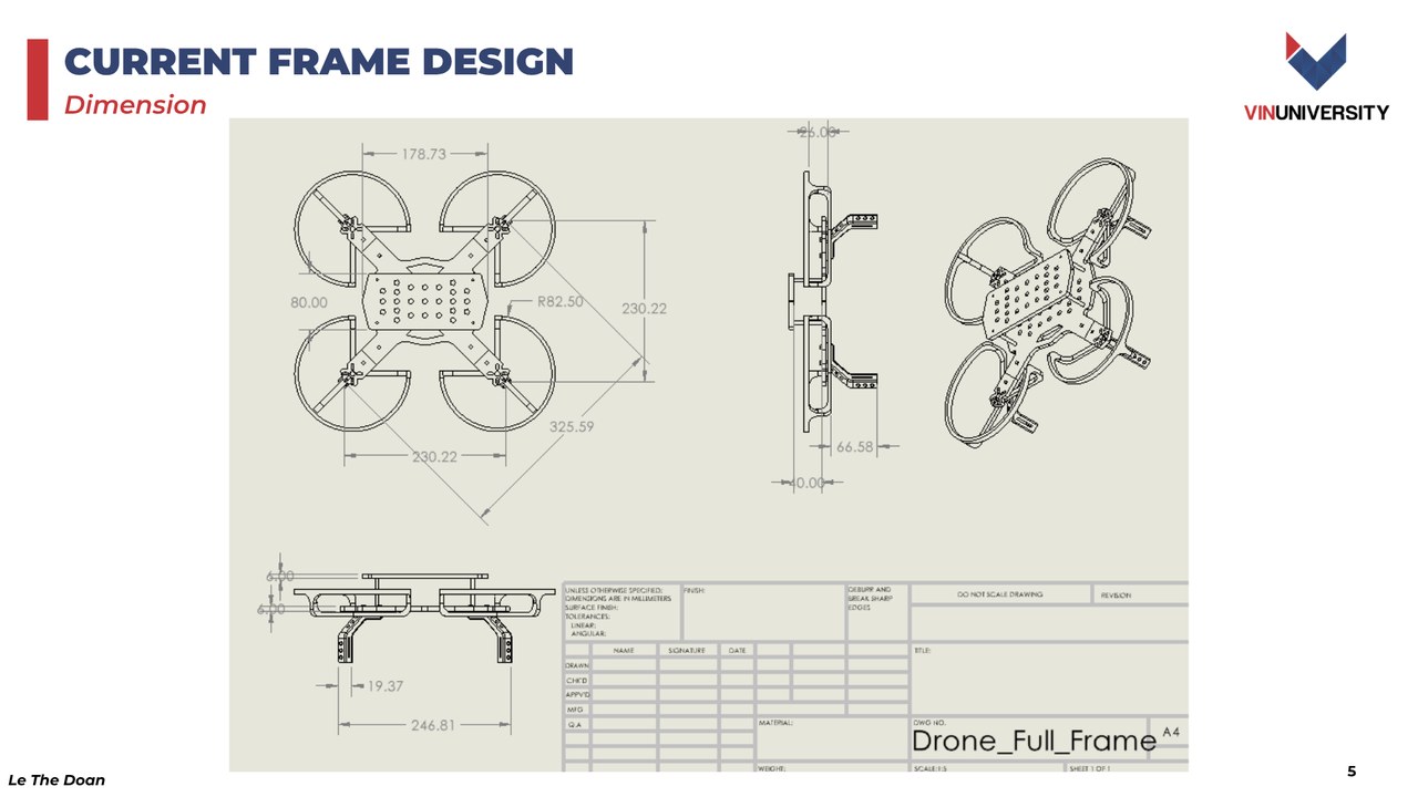
The final design utilizes a 178.73 mm diagonal wheelbase Quad-X configuration, manufactured via a hybrid combination of CNC-milled 3 mm Carbon Fiber base plates and reinforced 8 mm, 60%-infill 3D-printed motor arms:
2. Propulsion & Power Electronics Integration
The electrical propulsion subsystem was engineered to deliver a thrust-to-weight ratio > 2.2:1:
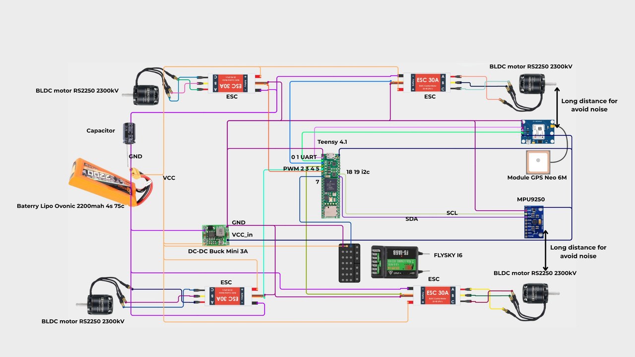
- Motors: Four RS2205 2300kV Brushless DC (BLDC) outrunner motors capable of delivering up to 1,024 g maximum thrust each on 5045 bullnose propellers.
- Speed Controllers: Four 30A Electronic Speed Controllers (ESCs) running BLHeli firmware, receiving low-latency PWM drive signals from the Teensy flight controller.
- Power Management: A 3S 11.1 V LiPo battery delivers high discharge current (up to 75C). High-power ground loops and motor back-EMF spikes are decoupled using a low-ESR electrolytic capacitor bank and dedicated LC filtering for the flight computer.
3. Real-Time Flight Controller Firmware & Sensor Fusion
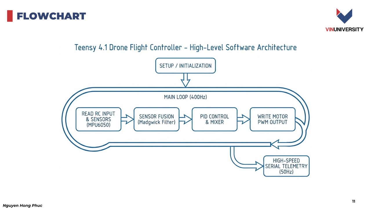
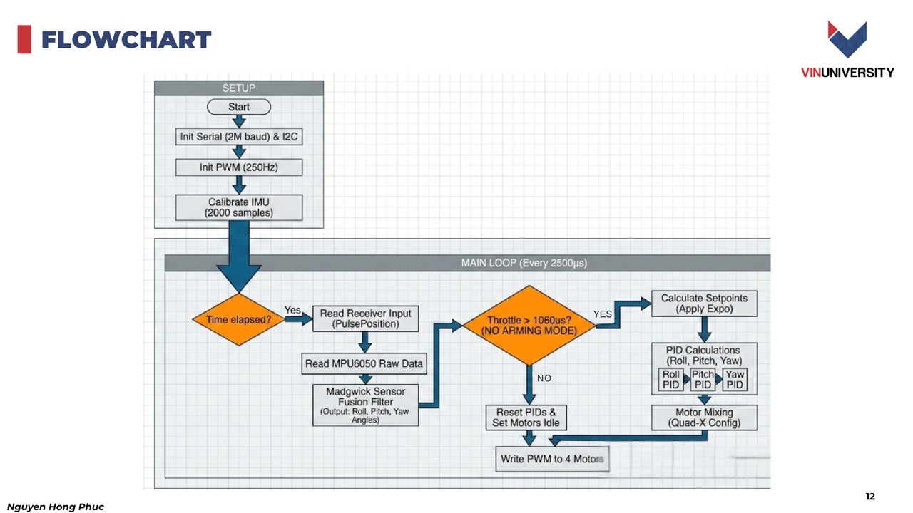
The flight control firmware was developed from scratch in C++ on the Teensy 4.1, taking advantage of the NXP i.MXRT1062 ARM Cortex-M7 running at 600MHz:
Madgwick Sensor Fusion Algorithm
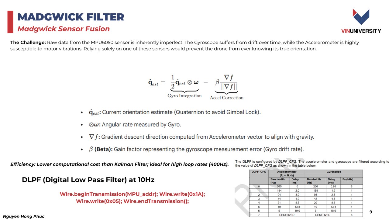
Raw data from the onboard MPU6050 6-DOF IMU presents significant challenges:
- Gyroscopes offer high responsiveness but suffer from unbounded integration drift over time.
- Accelerometers provide a reliable gravity reference in the long term but are easily corrupted by high-frequency motor vibrations and linear accelerations.
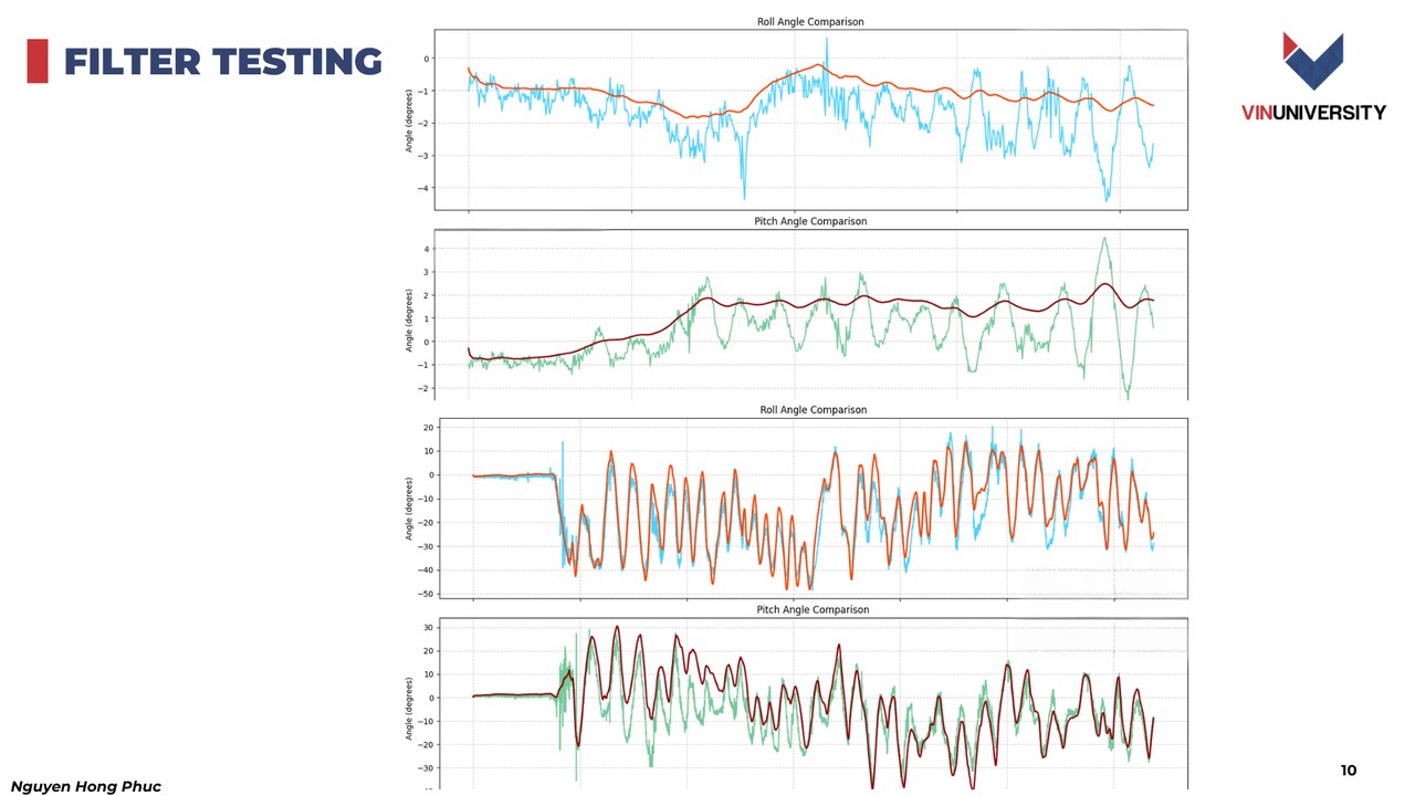
To achieve robust attitude estimation, we implemented the Madgwick Orientation Filter:
- Uses quaternion gradient descent to compute the direction of the gravity field from accelerometer readings, directly correcting the orientation computed from integrated angular rates.
- Achieves equivalent or superior accuracy to an Extended Kalman Filter (EKF) with vastly reduced computational overhead ($pprox 10\,\mu\text{s}$ per iteration on Cortex-M7).
4. 400Hz PID Attitude Stabilization & Telemetry
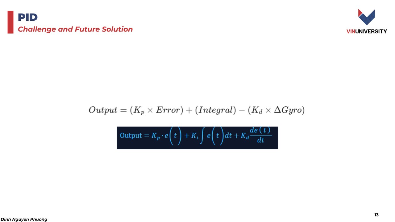
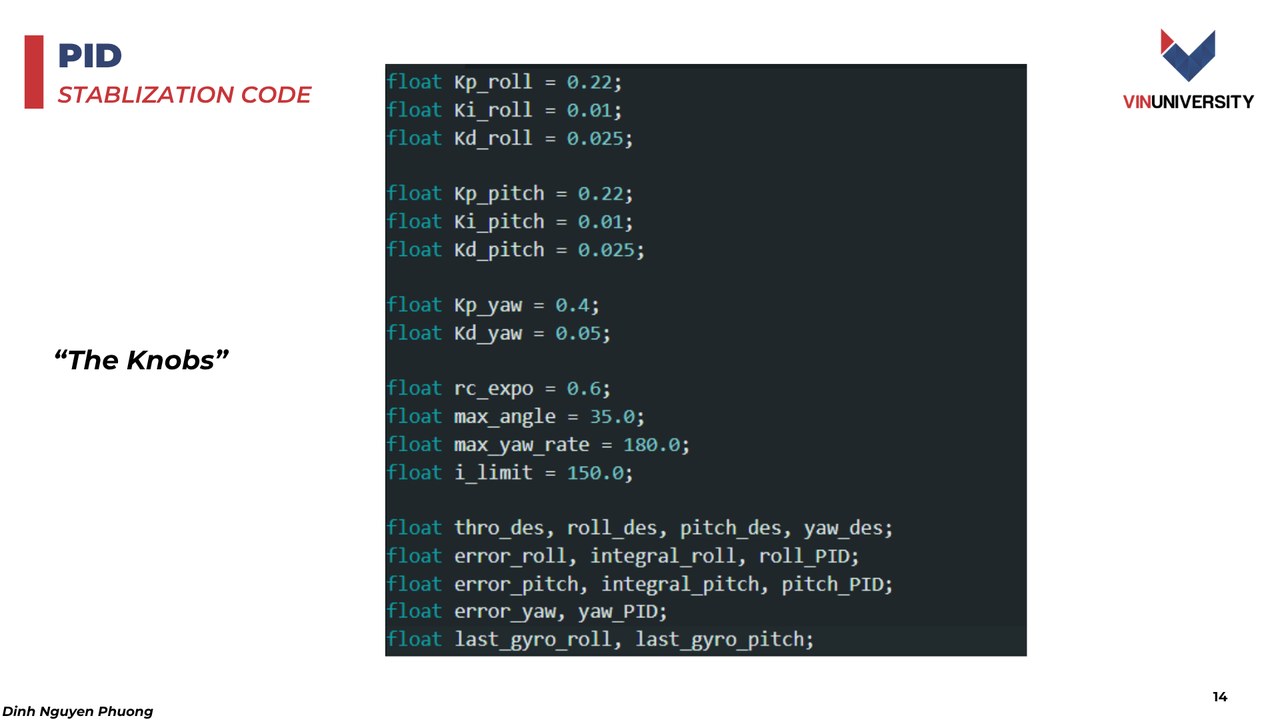
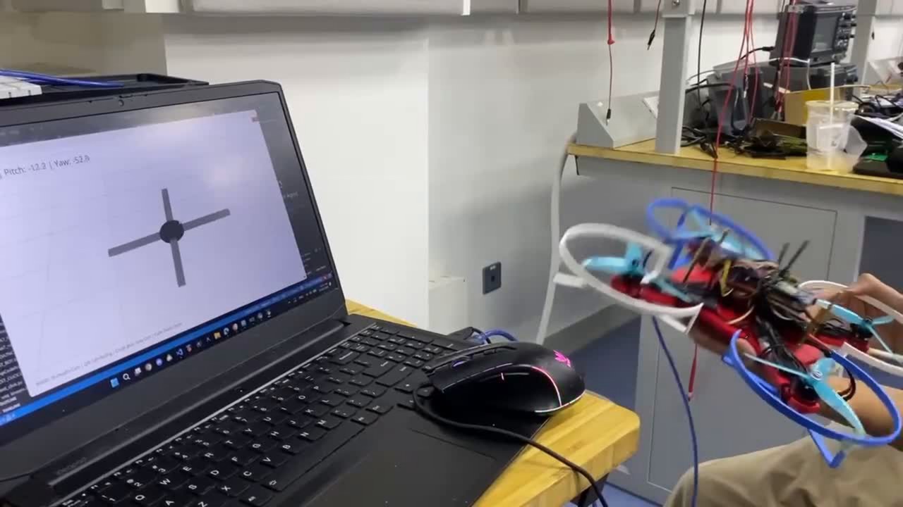
Attitude control is achieved through three independent Proportional-Integral-Derivative (PID) control loops operating on the Roll, Pitch, and Yaw axes at 400Hz:
\[u(t) = K_p \, e(t) + K_i \int_0^t e(\tau)\,d\tau + K_d \, \frac{de(t)}{dt}\]- Proportional (Kp): Provides instantaneous restoring torque proportional to orientation error.
- Integral (Ki): Eliminates steady-state attitude offsets caused by minor battery mass asymmetry or aerodynamic drag.
- Derivative (Kd): Dampens high-speed rotational oscillations and prevents angular overshoot.
Real-Time Loop Timing
Benchmarking confirmed a sustained loop execution frequency of 422Hz (cycle time T_loop = 2.37 ms), well exceeding the 400Hz target to guarantee deterministic motor update deadlines with zero jitter:
5. Experimental Validation on Test Jig
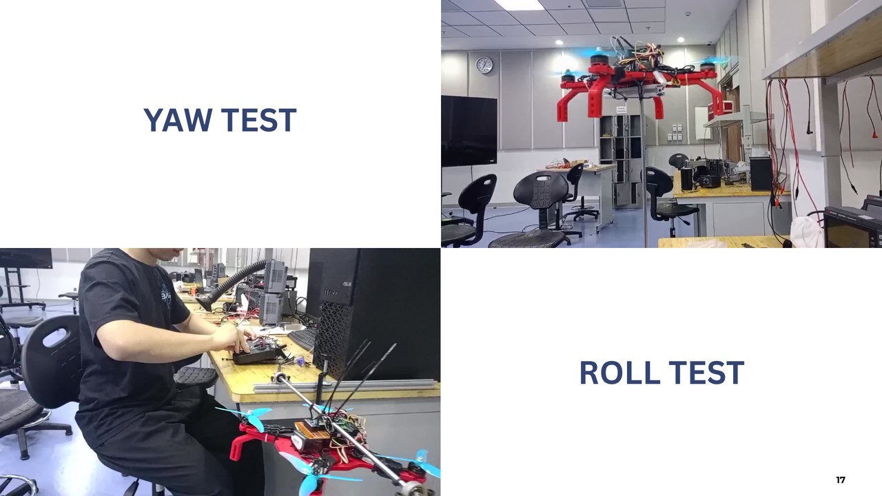
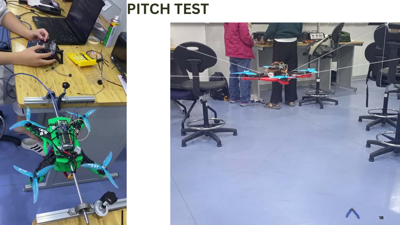
Before free-flight testing, the drone was constrained to an instrumented multi-axis test stand to tune PID gains (Kp, Ki, Kd) and evaluate step-response settling times:
- Roll & Yaw Step Responses: Tested disturbance rejection by applying sudden rotational impulses. The controller returned to level within < 180 ms with zero steady-state oscillation.
- Pitch Dynamic Tracking: Demonstrated tight setpoint tracking across rapid pilot input transitions from -20° to +20°.
6. Team & Project Information
- Course: ELEC3030 — Intelligent Physical Systems, VinUniversity
- Institution: College of Engineering & Computer Science, VinUniversity
- Team Members:
- Nguyen Hong Phuc (Embedded C++ Firmware Architecture, Madgwick Sensor Fusion, 400Hz PID Control Loop)
- Le The Doan (Chassis CAD Design, ANSYS Structural FEA Simulation, SolidWorks Optimization)
- Dinh Nguyen Phuong (Power Electronics, Propulsion Hardware Testing)
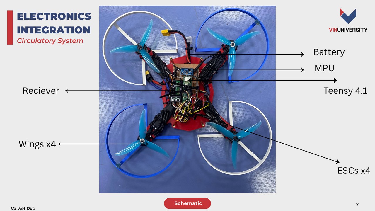
- Vo Viet Duc (Mechanical Assembly & Wiring)