Deep JSCC for Visible Light Communication
Hardware-in-the-loop Deep JSCC transmitting semantic features via analog light intensity using a custom 8-bit R-2R DAC.
A hardware-in-the-loop Deep Joint Source-Channel Coding (Deep JSCC) Visible Light Communication (VLC) system developed for ELEC4010: Introduction to Microelectronics at VinUniversity.
Unlike traditional digital communication that transmits raw binary bitstreams (0s and 1s) over discrete modulation schemes, this system compresses high-dimensional images into semantic latent representations (k = 16) using a Deep Convolutional Autoencoder and transmits them directly as analog light intensities via a custom-built 8-bit R-2R resistor ladder DAC, op-amp buffer, and BJT emitter-follower driver.
Project Links & Documentation:
- GitHub Repository: phucngvinuni/DAC-JSCC
- Download Project Report: Full 18-Page Technical Report (PDF)
- Team: Nguyen Hong Phuc (Lead & Design) & Vo Viet Duc (Hardware Assembly)
🎥 Live Demonstration: End-to-End Optical Transmission
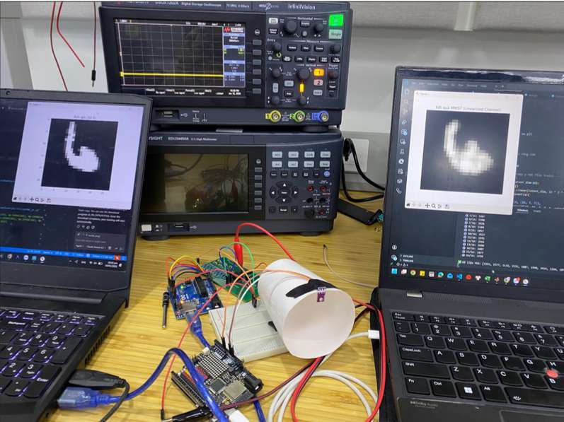
The video below demonstrates the complete end-to-end hardware-in-the-loop system in action. A transmitter PC encodes handwritten digits into 16 analog symbols, sends them through the 8-bit DAC and LED driver over free-space light to a TEMT6000 photodetector, and the receiver PC reconstructs the digit in real time:
Video 1: Hardware-in-the-Loop VLC Demo — Real-time transmission of handwritten digits from the transmitter PC to the receiver PC via analog light intensity modulation.
1. Motivation: Analog Deep JSCC vs. Brittle Digital Transmission
Traditional Visible Light Communication (VLC / Li-Fi) systems transmit digitized bits using binary modulation techniques such as On-Off Keying (OOK) or Pulse Amplitude Modulation (PAM). For image transmission, raw pixels are digitized into hundreds or thousands of bytes:
- Transmitting a single 28 × 28 grayscale image (e.g., MNIST) requires 784 bytes (6,272 bits).
- In low Signal-to-Noise Ratio (SNR) or turbulent optical conditions, a single corrupted bit can cause catastrophic bit errors or desynchronization (the “cliff effect”).
The Deep JSCC Paradigm:
Rather than separating source compression and channel coding, our system uses a Deep Convolutional Autoencoder to jointly compress the source image and encode it into continuous semantic features (k = 16). Each feature is mapped directly to a continuous analog light intensity. When channel noise occurs, the reconstructed image experiences smooth, graceful degradation rather than total structural failure.
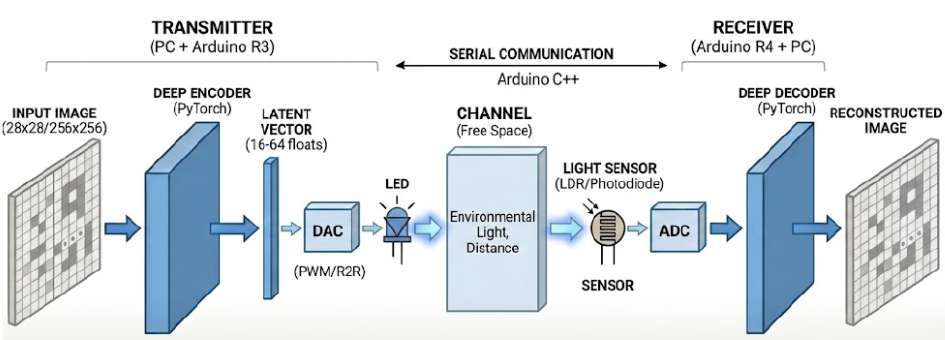
Benchmarking: Analog JSCC vs. Traditional Digital UART
| Metric | Traditional Digital Transmission (UART) | Proposed Analog Deep JSCC |
|---|---|---|
| Data Representation | Raw Pixels (Digital Bits) | Latent Semantic Features (Analog Voltages) |
| Payload Size | 784 bytes | 16 analog symbols |
| Channel Symbols | 6,272 bits (1 byte/pixel) | 16 physical optical pulses |
| Noise Resilience | Brittle (single bit-error corrupts pixel) | Robust (graceful degradation) |
| Transmission Speed | 1× (Baseline) | ~50× faster |
| Bandwidth Savings | Baseline (0%) | ~98% compression |
2. Microelectronics Circuit Design & Hardware Implementation
The hardware layer converts parallel 8-bit digital words from an Arduino into precise, continuous analog optical levels across three tightly coupled circuit stages:
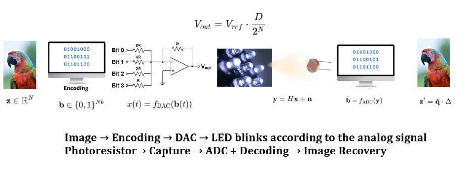
Circuit Topology & Stage Breakdown
- 8-bit R-2R Ladder Network:
Constructed from precision 1% metal film resistors (R = 1 kΩ, 2R = 2 kΩ). Driven by 8 digital GPIO pins (0–5 V), the ladder produces 256 discrete analog voltage steps:
with an ideal step size (LSB) of V_LSB = 5 V / 256 ≈ 19.53 mV.
- LM358 Op-Amp Voltage Follower (Buffer):
The raw output impedance of an R-2R ladder equals R = 1 kΩ. Connecting a load directly causes substantial voltage sag. Feeding $V_{\text{DAC}}$ into an LM358 op-amp configured as a unity-gain buffer ($V_{\text{out}} = V_{\text{in}}$) provides near-infinite input impedance (> 1 MΩ) to prevent loading, and low output impedance to drive the subsequent stage. - 2N2222 BJT Emitter-Follower LED Driver:
Standard op-amps cannot supply high continuous drive currents. The buffered analog voltage drives the base of a 2N2222 NPN BJT in emitter-follower configuration. With current gain β ≈ 100–300, the emitter supplies proportional current through a high-brightness Blue LED. - Isolated Optical Channel & TEMT6000 Receiver:
The transmitter LED and TEMT6000 phototransistor receiver are aligned within a light-shielded cylindrical optical tube to eliminate ambient room lighting interference. The sensor’s analog output is sampled by the receiver’s ADC.
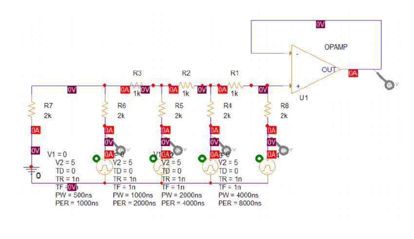
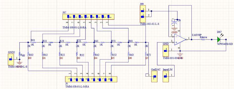
Simulation & Experimental Hardware Setup
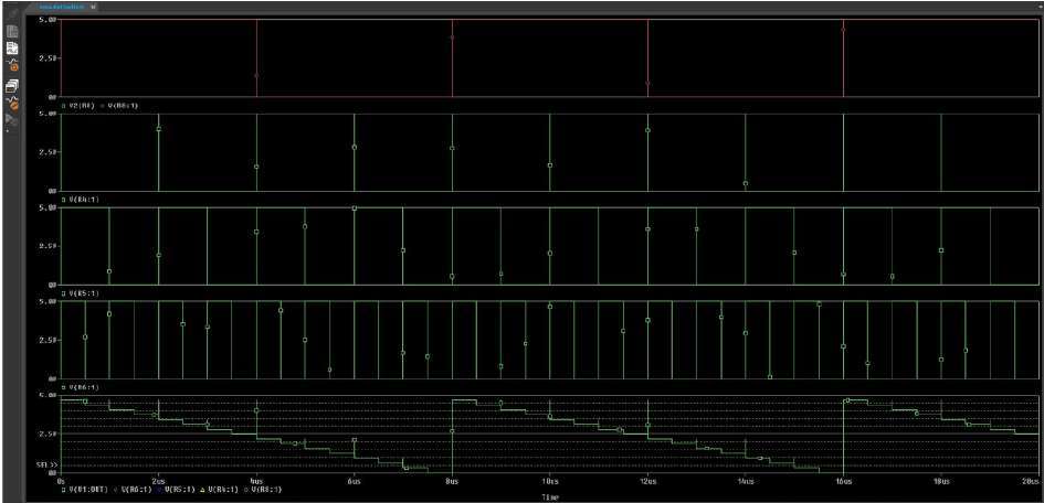
Prior to breadboard fabrication, the ladder and buffer stages were simulated in PSpice to verify step uniformity and monotonicity:
3. Physical Channel Characterization & Differentiable Learning
Real optical hardware deviates substantially from textbook linear models. Accurately characterizing physical non-linearities and embedding them into the deep learning pipeline was essential for reliable communication.
Physical Non-Linearity & Noise Analysis
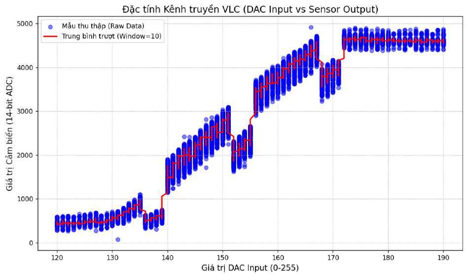
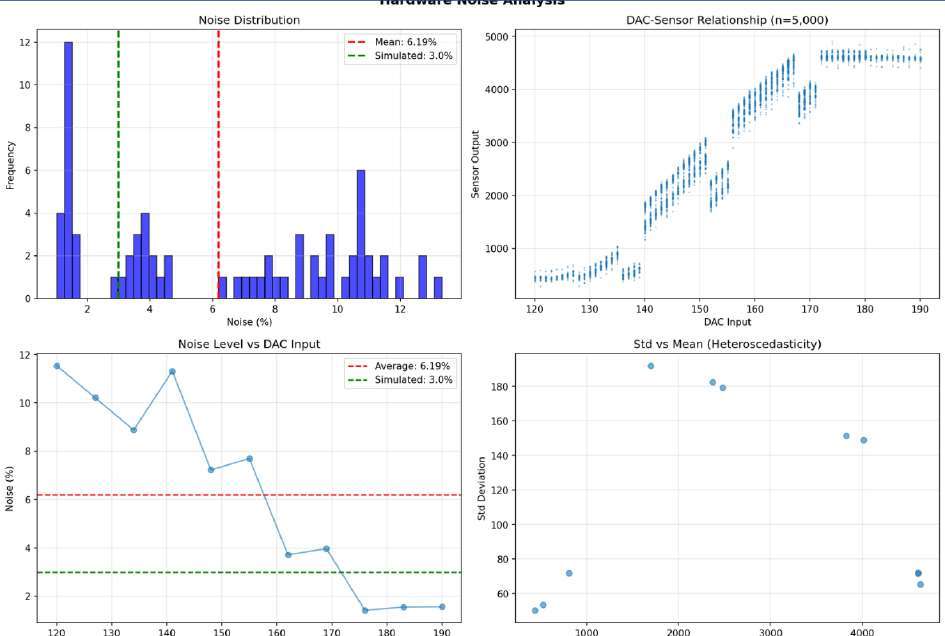
To model the physical link, we collected an empirical dataset of 5,000 samples (final_merged_dataset.csv) sweeping DAC input values from $0$ to $255$ and recording photodetector ADC responses:
- Non-Linear Transfer Characteristic:
The Blue LED requires a threshold voltage (V_th ≈ 2.7 V) before conducting significant current. Below D ≈ 120, the LED emits negligible light (dead zone). At high DAC values (D > 180), current saturation and phototransistor non-linearity cause response flattening. - Heteroscedastic Hardware Noise:
Analysis revealed that noise is heteroscedastic — the standard deviation σ_noise is not constant but scales with optical intensity (shot noise and optical fluctuations dominate at higher illumination).
Dynamic Waveform Validation
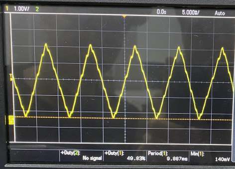
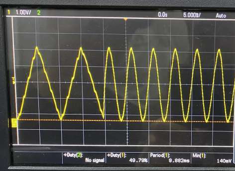
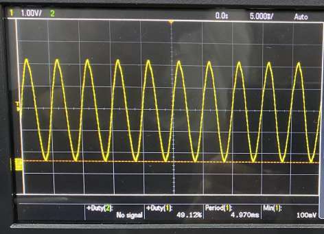
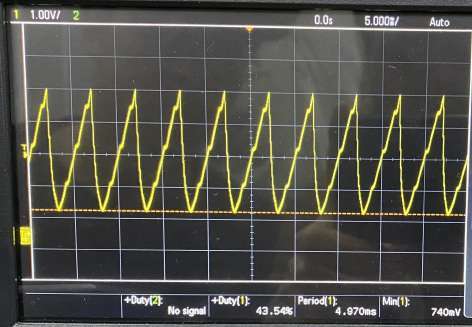
Oscilloscope measurements across multiple dynamic input trials confirmed high signal stability (consistent period $\approx 4.9\,\text{ms}$), discrete quantization steps, and monotonicity across full sweeps:
Channel Linearization & Differentiable Approximation
To enable gradient-based backpropagation through the physical channel:
- Channel Linearization (
createlinear.py):
We isolated the monotonic, high-sensitivity operating regime (D ∈ [140, 170] corresponding to V ∈ [2.74 V, 3.33 V]) and constructed an optimal mapping table (good_dac_map.json). - Differentiable Channel Layer (
real_channel.py/trainlinear.py):
During training, the PyTorch autoencoder uses a differentiable hardware-in-the-loop simulation layer that applies the empirical transfer function and heteroscedastic noise distribution. This allows the neural network to learn feature encodings that are inherently robust to optical non-linearities and physical noise.
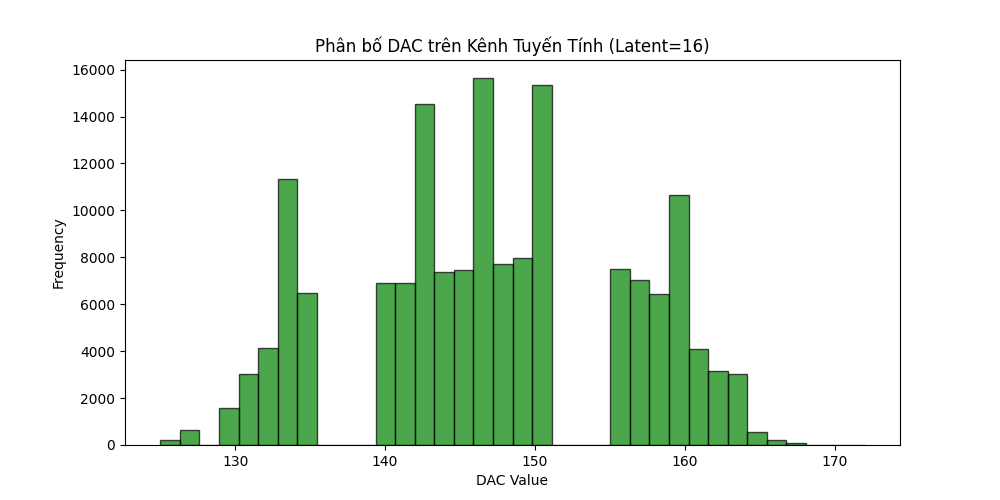
4. Experimental Results & Performance Evaluation
The end-to-end system was evaluated on the MNIST dataset using a latent dimension of k = 16.
Semantic Reconstruction Quality
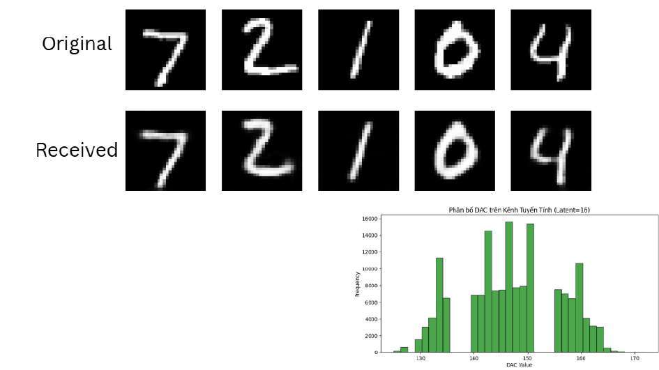
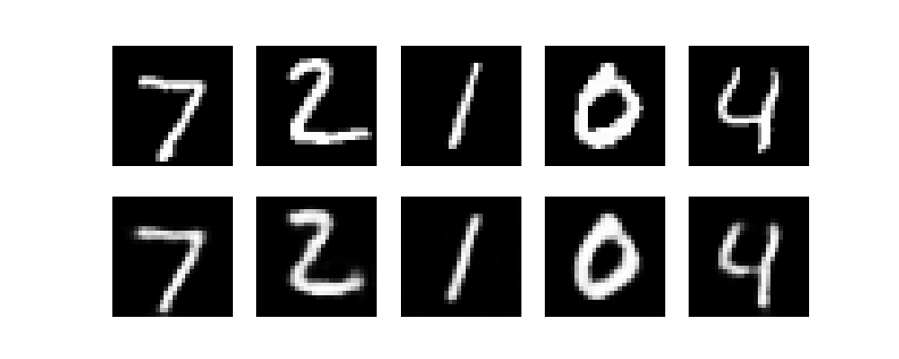
Despite compressing 784 image pixels into just 16 analog light pulses (98% compression), the receiver neural decoder faithfully reconstructed digit semantics, stroke continuity, and morphology under real physical channel noise:
Power Consumption Analysis
To measure current consumption through the R-2R network without breaking the circuit, the Voltage Drop method was applied across individual branches:
- Total current consumption of the R-2R ladder remained minimal at approximately 1.69 mA during peak operation.
- The emitter follower efficiently sourced current directly from the 5 V rail, preventing any loading or thermal drift on the precision ladder resistors.
5. Bill of Materials & Technical Specifications
| Component | Function / Specification | Quantity |
|---|---|---|
| Arduino Uno / R4 | Microcontroller for 8-bit parallel GPIO control & 10-bit ADC sampling | 2 |
| Precision Resistors (1kΩ, 1%) | R-2R Ladder Series Resistors ($R$) | 9 |
| Precision Resistors (2kΩ, 1%) | R-2R Ladder Shunt Resistors ($2R$) | 8 |
| LM358 Operational Amplifier | Dual General-Purpose Op-Amp configured as Unity-Gain Buffer | 1 |
| 2N2222 NPN BJT | Emitter-Follower Current Buffer for LED Drive | 1 |
| High-Brightness Blue LED | Optical Transmitter ($\lambda \approx 460\text{–}470\,\text{nm}$) | 1 |
| TEMT6000 Sensor | Silicon NPN Phototransistor Ambient Light Sensor | 1 |
| Optical Enclosure | Cylindrical light-shielded optical isolation chamber | 1 |
6. Credits & Project Information
- Course: ELEC4010 — Introduction to Microelectronics, Fall 2025
- Institution: College of Engineering & Computer Science, VinUniversity
- Authors:
- Nguyen Hong Phuc (System Architecture, Circuit Design, PSpice Simulation, Deep JSCC Autoencoder, Hardware-in-the-Loop Integration)
- Vo Viet Duc (Hardware Assembly)
- Supervising Faculty: VinUniversity Microelectronics Faculty
- Source Code & Report: GitHub Repository · Download Report (PDF)